By Dr. Christopher Kent
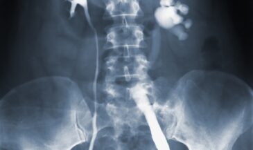
The primary purpose of spinal radiography in chiropractic practice is the analysis of vertebral subluxations. Chiropractors who employ x-ray examinations should be skilled in identifying unusual findings. Such findings should be disclosed to the patient or practice member.
Airline pilots routinely use check lists regardless of their level of skill and experience. Similarly, the use of check lists when evaluating radiographs significantly reduces the likelihood of error. The chiropractor who employs a systematic approach to the analysis of spinal radiographs will miss fewer unusual findings than the practitioner who uses a haphazard “hit or miss” procedure. The use of these procedures will also assist the doctor in developing good film reading habits which will eventually become “second nature.”
This month, and in upcoming columns, you will be presented with a series of “check lists” for each commonly employed spinal view. Each list describes a scanning procedure, followed by a list of findings which may affect the chiropractor’s approach to adjusting. It should be emphasized that these lists are not all- inclusive. Each chiropractor is encouraged to develop customized protocols consistent with the needs of the individual receiving the adjustment and the techniques of the chiropractor.
From a pragmatic standpoint, the chiropractor will find that persons under their care fall into one of the following categories:
— Category 1. These patients have no unusual findings that make traditional adjusting techniques hazardous. They have good bone integrity, and thrust (HVLA) adjustments may be safely applied.
— Category 2. Patients in this category have weakened or softened bone, or developmental issues that may require the chiropractor to alter the adjusting technique. Adjusting procedures for such persons must be carefully selected. High velocity adjustments to osteopenic bone should be avoided. Gentle, judiciously applied adjustments may be employed instead.
— Category 3. These persons have unusual findings where the application of high velocity forces to the involved area may be problematic.
The chiropractor is encouraged to think in terms of assessing the safety and appropriateness of specific chiropractic techniques in a given case.
Lateral cervical
Procedure:
1. Check the posterior arch of atlas for fracture, non-union, occipitalization, or basilar invagination.
2. Check the ADI (atlanto-dental interval) for enlargement. A measurement exceeding 3 mm in an adult or 5 mm in a child may indicate a damaged transverse ligament, a congenital anomaly, or an inflammatory process.
3. Check for agenesis, fracture, or non-union of the dens.
4. Draw the following lines (in your mind or on the film):
A. Anterior body line.
B. George’s line.
C. Spinolaminar junction line.
This will divide the cervical spine into three columns:
A. Anterior column. Check the anterior bodies for evidence of osteophytes, syndesmophytes, or DISH. Check the vertebral bodies for evidence of fracture, dislocation, alterations of trabeculae, and alterations of density.
B. Middle column. The distance between George’s line and the spinolaminar line roughly defines the sagittal diameter of the spinal canal. A measurement under 12 mm may indicate stenosis. An unexplained increase of this measurement at a given segmental level may indicate fracture. When checking the middle column, the chiropractor should also look for abnormalities of the posterior joints.
C. Posterior column. Check the spinous processes for evidence of fracture. Determine any abnormalities which may be present, and determine the cause. Sesamoid bones in the ligamentum nuchae are common, and should not be misinterpreted as fractures.
5. Check the intervertebral disc spaces and vertebral end plates.
6. Check the retropharyngeal space, which is measured from the anterior portion of the C-2 body to the posterior border of the pharynx. This measurement should not exceed 7 mm. The retrotracheal space is measured from the anterior aspect of the C-6 body and the posterior border of the trachea. This measurement should not exceed 22 mm. An increase in either of these measurements indicates prevertebral hemorrhage or soft tissue swelling.
Selected findings:
Ponticus posticus
Non-union of posterior arch
Fracture of posterior arch
Fracture of dens
Non-union of dens
Agenesis of dens
Increased ADI
Degenerative joint disease
DISH
Ankylosing spondylitis
Reiter’s syndrome
Psoriatic arthritis
Spinous process fracture
Compression fracture
Non-segmentation
Cervical kyphosis
Metastatic carcinoma
Hemangioma
Laminectomy
Osteoporosis
Dislocation
Anterolisthesis
Retrolisthesis
AP open mouth
Procedure:
1. Check dens for fracture, agenesis, and non-union. Beware of overlap of the incisors or posterior arch which could simulate fracture.
2. Check atlas arches, particularly for fracture.
3. Note distance between dens and each lateral mass.
4. Check occipitoatlantal and atlantoaxial joints.
Selected findings:
Ununited dens (os odontoideum or os terminale)
Dens fracture
Agenesis of dens
Occipitalization
Basilar invagination
Burst (Jefferson) fracture
Unilateral atlas arch fracture
Lateral listhesis
Non-union of posterior arch
Lower cervical AP
Procedure:
1. Check tracheal shadow for deviation which could indicate a soft tissue mass or swelling.
2. Check spinous processes for spina bifida, fracture (double spinous process sign), and rotation.
3. Check uncinate processes for fracture and degeneration.
4. Check transverse processes for fracture.
5. Check pedicles for osteolytic activity and rotation.
6. Check vertebral end plates.
7. Check trabecular pattern.
8. Check for cervical ribs.
Selected findings:
Osteolytic metastatic carcinoma
Cervical ribs
Fractured transverse process
Fractured spinous process
Fractured uncinate process
Non-segmentation
Hemivertebra
Hemangioma
Soft tissue mass
Cervical obliques
Procedure:
1. Check foramina for alterations of size and shape.
2. Check pedicles for fracture or osteolytic activity.
3. Check joints for degeneration.
Selected findings:
Uncinate process exostosis, causing foraminal encroachment
Neurofibroma, causing foraminal enlargement
Fractured pedicle
Degenerative changes in posterior joints
Base posterior/vertex
Procedure:
1. Check atlas arches for fracture and non-union.
2. Check lateral masses for occipitalization.
3. Check dens for fracture and non-union.
Selected Findings:
Jefferson fracture
Unilateral arch fracture
Occipitalization
Dens fracture
Non-union of dens
Vertebral arch/articular pillar view
Procedure:
1. Check the articular pillars for compression and burst fractures. Compare left and right sides.
2. Check vertebral arches for fracture.
Selected Findings:
Compression fracture of articular pillar
—–
Next: Check lists for thoracic and lumbar spine radiographs.
References
- Colohan D. “Emergency Management of Cervical Spine Injuries.” Abbott Laboratories, Abbott Park, IL. 1983.
- Elliot J, Rogers L, Wissinger J, Lee J: “The hangman fracture: fracture of the neural arch of the axis.” Radiology 104:303, 1972.
- Erhardt R. “Roentgenology of the spine and pelvis notes.” Privately published, Atlanta, GA. No date.
- George A: “A method for more accurate study of injuries to the atlas and axis.” Boston Med Surg Journal 181:13, 1919.
- Jefferson G: “Fracture of the atlas vertebra: report of 4 cases and a review of those previously recorded.” British J of Surg 7:407, 1920.
- Kent C: “Protocols for the analysis of plain skeletal radiographs.” Digest of Chiro Economics 31(3): 70, 1988.
- Kent C: “A systematic approach to the evaluation of cervical spine radiographs.” International Review of Chiropractic September/October 1989.
- Lane E, Proto A, Phillips T: “Mach bands and density perception.” Radiology 121:9, 1976.
- Litterer W: “A history of George’s line.” ACA Journal of Chiro, December 1983, p. 39.
- Macrae J: “Roentgenometrics in Chiropractic.” Privately published. 1983.
- Resnick D, Niwayama G: “Diagnosis of Bone and Joint Disorders.” W. B. Saunders, Philadelphia, PA. 1988.
- Yochum T, Rowe L: “Essentials of Skeletal Radiology.” Williams and Wilkins, Baltimore, MD. 1987.


